


home, turning, wood, cad, contact, links, blog, disclaimer, about, site_map designed with Serif webplus, © copyright 2005 -


Symmetrical profiles -
With this Spline profile Fig 3.1, some nodes were deleted and the Ref point of the profile has also been moved to the intersection of the red centre lines
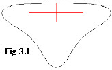
The profiles are placed into position snapping to the blue line, hope your not using a black & white monitor :-
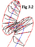
Now, either simply mirror copy along the blue line and boolean add together, or slice the lofting along the blue line, and then mirror copy along the slicing line, -
Problems -
Cause -
Solution -

Symmetrical profiles -
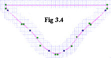
The next lofting uses a similar approach to half spline, but uses a bezier curve where tight corners in the profile can be utilised, Fig 3.4, but there are drawbacks, .the main one being editing the nodes, if you’ve ever tried editing your nodes you’ll see what I mean, can bring tears to the eyes
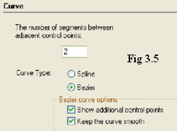
One thing to do when drawing the profiles is to go into properties Fig 3.5, experiment with the number of segments between controls points, in some circumstances it can make a difference, the more segments the slower things can get, think of it as quality versus price. Try it -
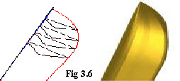
The loft is done in the same manner as the spilne, except that it’s possible to put the ref point on the ‘virtual’ vertex and snap to an outer guideline, Fig 3.6, when positioning the ref point, try with snaps on, zoom in, nearest on graphic, magnetic on, Sometimes vertex running snap will work. If you haven’t upset Genie too much
Problem -
Cause -
Solution, -


| turning a to b |
| turning c |
| turning d to g |
| turning h to l |
| turning m to o |
| turning p to r |
| turning s |
| turning t to z |
| turbocad drawings |
| turbocad_vehicles |
| turbocad Gas |
| Turbocad Fun |
| tc_animations |
| tc_anaglyph |
| turbocad topics |
| turbocad program details |
| Woods |
| blog |
| disclaimer |
| about me |
| serif related |